
A Gear one type of Mechanical element whose teeth are around the conical surface with the same space.
It is used to transmitting the power between one point to another point
Gear and their mechanical assembles are widely used in industry to the power in a variety of mechanical devices. Gear is also used to transfer rotational motion to a different axis.
It is used to transmitting the power between one point to another point
Gear and their mechanical assembles are widely used in industry to the power in a variety of mechanical devices. Gear is also used to transfer rotational motion to a different axis
CLASSIFICATION OF GEAR
Gears can be classified in various types according to the construction of teeth, use the direction of the motion transfer but the basic are classified according to the design of teeth. We will describe the most important type of it. The many types of Gear such as spur gear, helical gear, bevel gear, worm gear, rack, and pinion, etc.
We can also be classified with looking at positions of axes such as
•Parallel shafts
•Intersecting shafts
Non-intersecting and Non-parallel
Parallel shaft:-
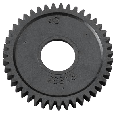
Spur gear:

The spur gear is used to transmit the power in the same plane or when the driving and driven shafts are parallel to each other.
In this type of gear, teeth are cut parallel to each other. In this type of gear, teeth are cut parallel to the meshes with another spur gear it transmits the power in parallel shafts and when it connects with helical gear it’ll transmit power at an angle from the driving axis.
The most common gear are spur gears and are used to series for large gear reductions. The teeth on spur gear reductions. The teeth on spur straight and therefore the mounted in parallel on different shafts. Spur gear used in washing machines, screwdrivers, Windpumps, alarm clock, and other devices. There are particularly loud, because of gear tooth engaging and colliding .each impact makes loud noises and causes vibration which is why spur gears aren’t utilized in machinery like cars. NORMAL GEAR RATIO:1:1 TO 6:1
Helical Gear:
The helical gear’s teeth are cut an angle from the axis of it. It has a cylindrical roller with helicoid teeth .the main advantage of helical gear is that they work with less noise and vibration because,

The load is distributed on the whole helix as compared to spur gears. It also used to transmit power on the non-parallel shaft also. In the helical gears if the pinion is cut with right-handed teeth then the gear is cut with left-handed of in the opposite direction a dis-advantages of helical gear is curved teeth generate the thrust when the gear is under load, this is usually handled by a suitable thrust bearing to help take this load. The typical range of the helix angle is about 15 to 30 degrees. The thrust load varied directly the magnitude of the tangent of the helix angle. They are also generating large amounts of thrust and use bearings to help support the thrust load. Helical gears can be used the required rotation angle by 90 deg. When mounted on perpendicular shafts. NORAMAL GEAR RANGE 3:2 to 2:1
Double Helical(Herringbone) Gear:

•A double helical gear is similar to 2 separate helical gears joined together but mirrored , this help eliminate the thrust that a single helical gear would be create as in effect there equal thrust in each direction cancelling each other out.
This gear is use to provide addtional shear area on gear which further required for the higher torque transmission .
Rack and Pinion

•This gear is used in the steering system of an automobile . In this type of gear, teeth are cut on a straight rectilinear geometry know as rack and one spur gear known as the pinion .
•This is used to transmit rotary motion to linear motion. It is seen as the infinite radius driven gear. Exp. Stairlift, car steering, lock gates.
INTERNAL GEAR:
The cylindrical gears are teeth cut into a cylinder or cone and paired with external gears. The main uses of internal gears are the planetary gear and shaft coupling of the gear type. Due to in volute interface, trochoid interference, and cutting problems, there is a limit on the number of teeth between the difference between internal and external gears.
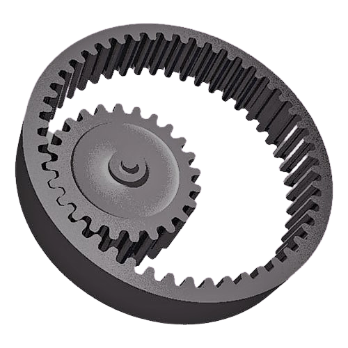
Many type Gear are available in market like internal spur gear ,internal bevel gear,internal helical gear, internal worm gear.
When the direction of rotation of the mesh of the internal and external gears are the same but opposite direction.
INTERSECTING SHAFT
STRAIGHT BEVEL GEAR:
•The bevel gear has cone-shaped which enables them to mesh at various angles except 0 to 180 degrees.
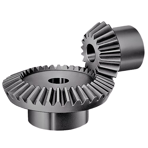
That is not to say a single bevel gear must be cut to suit a specific meshing angle. The teeth of a bevel gear can be straight cut, similar to that of a spur gears teeth, that called straight bevel gear.
•This gear is employed to transmit power between perpendiculars. The driving shaft and driven shaft make a right angle with one another and both the axis of shaft meets one another at one point. Bevel gear suited for low-speed applications usually subs 5m/s.
SPIRAL BEVEL GEAR:
The gear is helical spiral teeth on each conical-shaped geometry and meshes with the same gear.

Spiral teeth operate the same as helical gears. They produce less vibration and noise in comparison to straight teeth. The right hand of the spiral bevel is that the outer 1/2 the tooth, inclined to travel within the clockwise direction from the axial plane. The left hand of the spiral bevel travels in the counterclockwise direction. NORMAL GEAR RATIO 3:2 to 4:1.
This design greatly reduces the vibration and noise produced especially at high angular velocities (>1000). They are more difficult to produce.
The zero conical gears with a turning angle a of in a helical bevel gear are called null bevel gears.
HYPOID BEVEL GEAR:
In the hyped gear same as spiral bevel gear, the larger gear is called the crown while the small gear is called the pinion.

Hypoid gears are a type of spiral gear in which the shape is a revolved hyperboloid instead of a conical shape. the pinion off-axis to the ring gear IT IS The hypoid gear. This allows the pinion to be larger diameter and provide more contact areas.
The pinion and gear are often always opposite hand and the spiral angle of the pinion is usually larger than the angle of the gear ratios. NORMAL GEAR RATIO 10:1 to 200:1.
MITER GEAR:
Miter gear defined as a pinion or crown wheel and crown wheel with a speed ratio of 1. It is used to change the direction of power transmission without changing the speed.
When using helical miter gear, the thrust bearing generates a pulse in the axial direction and must be considered for use. In addition to a common miter gear with a 90-degree Shaft angle, a miter gear with a different shaft angle is called an angle miter gear.
NEITHER PARALLEL NOR INTERSECTING SHAFTS:
WORM AND WORM GEAR
•The screw gear shape that is cut on the shaft is a worm, the meshing gear is a helical gear, and the axes that do not intersect are called worm gears.

•The worm and worm wheel are not limited to cylindrical shapes there is a type of hourglass that can increase the contact rate, but the product becomes difficult it is necessary to reduce friction due to the sliding contact of the gear surface.
• For this reason, hard material is generally used for the worm wheel.The rotation is smooth and quiet even if the efficiency is low due to the sliding contact.
•If the angle advance of the worm is small, an automatic block is created.
SCREW (CROSSED HELICAL) GEAR:
•The screw gear is a pair of hand gears with a 45-degree angle of rotation on parallel axes that do not intersect.

•Since the contact of the tooth is a point, the load capacity is low and is not suitable for high power transmission. Since the force is transmitted by the sliding of the tooth surface, it’s necessary to concentrate on the lubrication when using the screw gear. There is no limit to the number of tooth combinations.
